There are 2 wiring methods for the RTD module and PT100 temperature sensors — twowire and threewire connections When wiring with two wires, first jumper across A1 and B1and and B2 respectively, then connect PT100 sensors and to the RTD module according to the following diagram on the left (Note A1B1, B2 and C1C2Oct 10, 13 · An ignition module is the component in electronic ignition systems that functions as the contact breaker for the coil or coils In most basic terms, an ignition module is an electronic replacement for old, mechanical contact breakers like ignition pointsCapacitors to operate Refer to the enclosed wiring diagrams Capacitors and relays must be sized for the specific motor Capacitors are sized based on ideal conditions The run capacitor may need to be resized to match the available field voltage Each cap kit shipped is supplied with a wiring diagram and start up procedure Pg 3

1998 Ford Expedition Engine Diagram More Diagrams Stage
Tp 100 module wiring diagram
Tp 100 module wiring diagram-Nov 01, 13 · 12way (Row) SPN = 12 X 1SP= 12Nos (Module) of single pole MCB as outgoing feeders Normally single phase distribution is mainly used for small single phase loads at house wiring or industrial lighting wiring 2) TPN Distribution Board (Incoming, Outgoing) 4way (Row) TPN = 4 X TP= 4nos of 3pole MCB as outgoing feeders =12 No of single pole MCBTYPICAL INSTALLATION – MODEL TP2 The TP2 senses the electical power input to a motor (horsepower) The Output is a 4 Milliamp LOOP POWERED analog signal proportional to power 505 368HP 755 552HP 1005 736HP 1505 110HP 05 147HP 3005 221HP 4005 294HP 5005 368HP 7/07
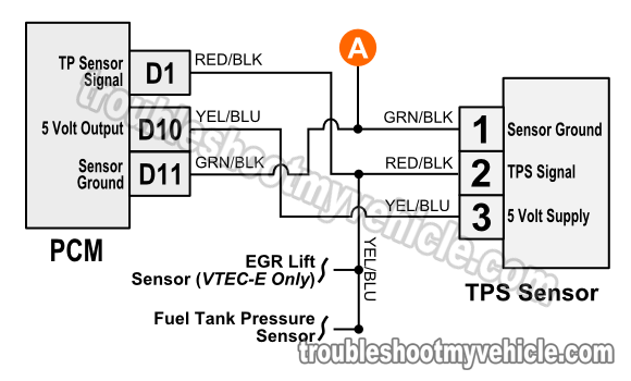


1996 1998 Throttle Position Sensor Circuit Diagram 1 6l Civic
Complete protection of AUMA pottype motors is only achieved when correctly wiring the thermoswitches, embeddedDicktator installation training course;R R TP100 Ignition Spark Module quantity
Aug 07, 18 · Tp100 Wiring Diagram efcaviation design tp100 wiring diagram phptp wiring diagram diagrams facbooik with template 7 diagram diagrams tarako citroen berlingo radio mulliveemasin mysoda tp frog ee wiring gotech pain the volkswagen club of south africa afabqqe coil mashups bosch ignition module electronic ford Tp100 Wiring Diagram dk tp100Nov 15, 16 · 2Wire RTDs These are as simple as it gets, only one wire per side You may need to calibrate the sensor by putting it in an ice bath to get the resistance at 0 ° C (say 102 Ω) and then subtracting 100 Ω to figure out the collective resistance of the connection wires!Sep 13, · Variety of pt100 sensor wiring diagram A wiring diagram is a streamlined conventional pictorial representation of an electric circuit It shows the parts of the circuit as streamlined forms, and the power and signal links in between the devices
Y0001/002/en Connections of motors AUMAmotors For DC, brake and twospeed motors, separate terminal plans are available ATTENTION !Wiring diagram 240 v 2 wire and ground clock motor 1 vac, 60 hz clock motor voltage and cycle must be as specified to order replacement, indicate part no (wg) on motor cover time pointer time dial off tripper manual lever on tripper typical wiring diagram clock motor 1/240 volt 3 wire supply to loads ground line 2 line 1 a 2 4 gr 1Page 30 73 ASS'Y DISPLAY PCB(18K/24K) DBC Parts List Description Specification Q'TY Remark ASS'Y LED MODULE GREEN PCBDISPLAY FR1 T16 TACT SWITCH KPT1105A RESISTOR 0ohm, 2W CONNECTOR WIRE Samsung Electronics


Suzuki Fiero Wiring Diagram Wiring Diagram Schedule


Ignition Modules Diesel Electric
Page 35 Wiring Diagrams 7 Wiring Diagrams 71 Indoor Unit Code No DBA Samsung Electronics Page 36 72 Outdoor Unit SH24TP6(A)X / UQT24P6GE DIAGRAMOUTDOOR Code No DBA UQT24P6GB DIAGRAMOUTDOOR Code NoMay 17, 21 · and wiring and various connectors for the sensors, injectors, etc, In this section we will cover the requirements for these components Note that injector wiring specifics are in the Injectors & Fuel Supply section External Wiring Schematic (This wiring diagram is for those creating their own harness for a V22 main boardUniversal car dash race display;
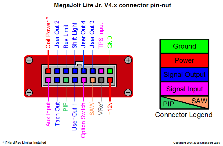


Mjlj V4 Vehicle Installation Guide Autosport Labs


Project Hei Module External Coil Install Mazda Mx 6 Forum
Block Diagram fosc 100KHz PWM & PFC EMI FILTER RECTIFIERS CIRCUIT POWER SWITCHING FILTER & RECTIFIERS I/P V2 FG CONTROL OVP & PFC DETECTION CIRCUT RECTIFIERS FILTER & REGULATOR V3 & FILTER RECTIFIERS COM 5V 5 90 100 80 70 60 50 40 File NameTP100SPEC 100WTriple Output with PFC Function TP100 series 0 142 25 8 max 133 65 117PLUG & PLAY HARNESS PLUG N PLAY HARNESS;Most of the wiring in the harness has been preterminated to the proper connector and all wire is rated at 125°C and has been GM colorcoded These fuel system harnesses have been divided into three major groups ENGINE GROUP Includes wiring


Mk3 Cli Rev Counter And Oil Light Connected To Tsz H The Volkswagen Club Of South Africa
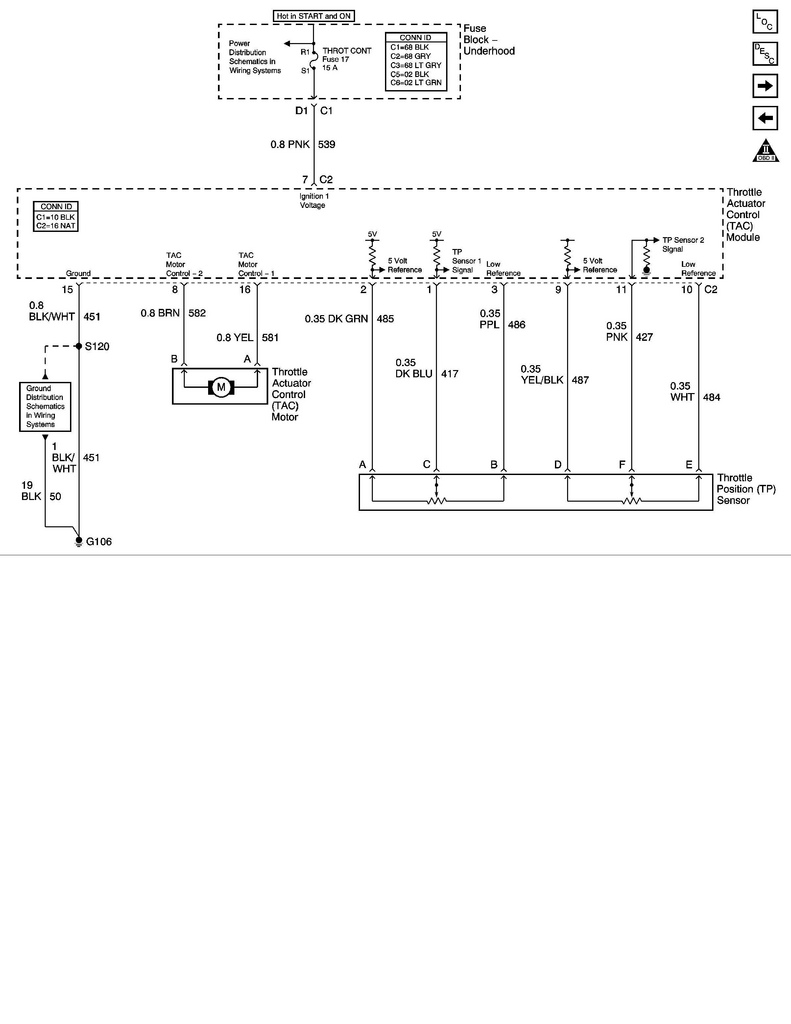


Ls1 To Ls2 Throttle Position Sensor Wiring Swap Questions Corvetteforum Chevrolet Corvette Forum Discussion
Jan 05, 14 · 3 wire pt100 wiring diagram welcome to my site, this message will discuss concerning 3 wire pt100 wiring diagram We have actually gathered several pictures, with any luck this photo is useful for you, as well as help you in finding the response you are trying to find Description Temperature Sensing – Maxim –Jul 04, 19 · You should follow the wiring diagram ensuring you place the single white wire (for 3 wire) on one side of the circuit and the two red wires on the other The output will normally only have two terminals as a 4mA device will almost certainly be loop powered In other words, the 2 wires connected to the output provide the power supply in butTry our configure tool to find the variant to fit your specifications Quotation Curves Drawings Dimensional Drawing Wiring Diagram 3D Loading Show 3D 3D Top Left Front Right Bottom Back Close Download CAD/BIM drawings Select all Download


01 Gmc 2500hd Sierra Cruise Control Quit Functioning Gm Truck Club Forum


Zing Ear Tp 01 Zh Touch Lamp Light Dimmer Switch Control Sensor Amazon Com
Apr 08, 14 · Unfortunately it was/is used on a multitude of tractors but I think that long ago they stopped publishing the electrical wiring diagrams in the operators or parts manuals I have looked for diagrams on several of the newer generation of tractors and all I have been able to find are images of the wiring harness that really gives no insight intoModuSat (TP) Twin Plate Satellite Heating Unit Installation, Commissioning and Servicing Instructions B Evinox Energy Ltd T 44 (0)1372 E info@evinoxenergycouk W wwwevinoxenergycoukMay 27, 10 · Step 1 Locate Ignition Module To locate the ignition module, refer to a wiring diagram for your vehicle's particular make and model As you might guess, the placement can change based on the type of vehicle, so it is important to have the correct diagram or you will be practically going in blind


Tp 0649 001c Diebold 816 Audio One On One Installation And Operating Instructions


Tp 700 Instruction Manual Detcon
Transmits an HDMI signal to the receiver up to 100m distance via a twisted pair cable Featuring bidirectional IR, Ethernet and RS232, you can control your display or source using the included accessories With bidirectional PoE power, you only need to connect the power supply on one end 12 Features • EDID pass through • HDCP 22 compliantOct 17, 17 · I need help with the wiring for the TP100 with the harness, I dnt want to burn the module or anything else Three wires , one red, one blue and one green and white that has an eye terminal on it Correct me if I am wrong here Red will go to the positive of the coil, blue will go the negative and the green&white wire ????Oct 07, · Ha 2468 Advance Ballast Wiring Diagram On Philips Free 7 way diagrams full 96 electronic sony xav 63 liter gm engine thermostat 71 460 ignition coil ge ac replacing a bad r tp 100 metal halide 4 page line 17qq com nema 34 53 cadillac blue sea wiring semi 80 yamaha warrior renault 19 of blood tissue automotive
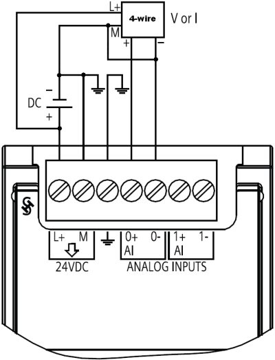


How Do You Connect A Sensor To The Analog Signal Modules Of The S7 10 S7 1500 An Id Industry Support Siemens
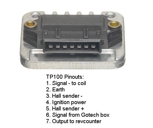


Convert To Electronic Ign Page 2 Aircooled Vw South Africa
Jan 26, 10 · TP 100 module wiring Search Advanced search 6 posts • Page 1 of 1 16V Dub Cadet I need some help with my module wiring I'm not getting spark from coil wire Called a friend over with his CTi, i tried my module on his car and it works fine it seems like diagram for gotech management Module, coil and dizzy works fine when testedTURBO CONVERSIONS STAINLESS STEEL FABRICATION;A wiring diagram is a straightforward visual representation of the physical connections and physical layout of your electrical system or circuit It shows how a electrical wires are interconnected which enable it to also show where fixtures and components may be coupled to the system


How To Wire Mid 1970s Through Mid 1980s Ignition System With A Gm Ignition Module Mopar Forums


1996 1998 Throttle Position Sensor Circuit Diagram 1 6l Civic
Home / IGNITION MODULES / TP100 Ignition Spark Module TP100 Ignition Spark Module R R Sale!WARNING Do not connect AC line power to the 2wire module Severe damage will result Important Notes 1 Use wiring practices that conform to all national, state, and local electrical codes 2 DO NOT run sensor cables or instrument 4 mA output wiring in the same conduit that contains AC power wiringWhile a separate FTA of a given type is required to handle varying field wiring signal levels, identical I/O Processors can usually be used This I/O approach simplifies system hardware selection and minimizes spare parts requirements For example, one Digital Input Processor can handle 24 Vdc, 1 Vac, 125 Vdc


Tp100 Module Wiring Diagram Phone Handset Wiring Diagram


Wiring Different Tp 100 Wiring Diagram
Apr 27, 18 · rtd pt100 3 wire wiring diagram – A Beginner s Guide to Circuit Diagrams An initial look at a circuit layout might be complicated, yet if you could check out a subway map, you can check out schematics The function coincides receiving from point A to aim B Literally, a circuit is the path that permits electricity to circulation If youJun 07, 17 · A further possibility to substantially decrease the influence of the cabling is to increase the conductor crosssection With a crosssection of 05 mm 2 the line resistance is only 0036 Ω/m or 01 °C/m Both options (3/4wire connection or increasing the crosssection) lead to a higher cost in the cabling, which can be problematic, especially in costsensitive markets suchTP100 Product specifications Product Support Customer and Technical Support, Training, Software/Firmware, Repair Services


Wiring Diagram 1997 Pontiac Grand Am Wiring Diagram Database Action


Wiring The Enc28j60 Ethernet Module On Arduino With Relay 14core Com
How to Test an Ignition Control Module Remove one plug wire at the spark plug and insert an old spark plug into the end of the plug boot Check for voltage at the coil positive terminal when the ignition key is on Locate the ignition module positive () wire Locate the ignition module negative () wireDicktator dbw system – (drive by wire ecu) dicktator maps;Variants TP /2 AFABAQENX1 Specifications Can\'t find the variants that fits your need?


Zing Ear Tp 01 Zh Touch Lamp Light Dimmer Switch Control Sensor Amazon Com


How To Wire Mid 1970s Through Mid 1980s Ignition Systems Retrofitting Electronic Ignition On Vehicles That Originally Had Points Allpar Forums
Listed below is the vehicle specific wiring diagram for your car alarm, remote starter or keyless entry installation into your Toyota T100This information outlines the wires location, color and polarity to help you identify the proper connection spots in the vehicleSizing and selection tools, quick dimensioning, pump replacement tools, CAD drawings, pump curves and other relevant dataHome / Engine Management Systems / TP100 Ignition Module TP100 Ignition Module R TP100 Ignition Module quantity Add to cart SKU 094 Category Engine Management Systems Product ID 1678 Reviews (0) Reviews
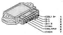


Bmw Airhead Motorcycle Ignition


Tp 100 Conversion For 2 And 3 Wire Distributors Wiring Len Flickr
Jun 17, 19 · Assortment of rtd pt100 3 wire wiring diagram A wiring diagram is a streamlined standard photographic depiction of an electrical circuit It shows the components of the circuit as streamlined shapes, and also the power and also signal links between the gadgetsIs it necessary to program a new tp100 module no spark at coil but seem to get power at the coil plug as well as on Volkswagen 07 Citi 14i question Search Fixya An expert who has achieved level 2 by getting 100 points AllStar An expert that got 10 achievements MVP An expert that got 5 achievementsNov 19, 08 · Based on the information of the suggested S7300 Module Datamanual, it looks like you should be connecting your SM3311KF01 module to the 2wire RTD through pins M and M, with a short from M to S (pins 25, 24 and 23 in Channel 4, in the example) They also add the following note about module signal grounding Note


Tp100 Wiring Diagram Vw Subaru Conversion Engine Wiring Harness 5pin Asyikk Masuk1 Waystar Fr


Ignition System With Hall Effect Sender
Jul 22, 10 · Ignition Module Circuit Descriptions The ignition control module has two connectors Looking down at the ignition module (with the ignition module still bolted in place), you'll notice that the ignition control module has a left connector and a right connector In the pin out charts below is a brief job description of what each wire doesYou may also need to test voltage and resistance at wiring, connectors and individual components with a (Digital Volt Ohm Meter), which you'll also find on our digital shelves If testing points to a faulty receiver, control module, or other TPMS component, there's no reason to pay high dealer prices for a replacementAftermarket TP100 Ignition Module of High Quality built by Dicktator with high qulaity electronic IGFET components These Modules have no internal electronic rev limiter such as the VW TP100 Modules and are compatible with any engine management system, aftermarket or standard(for eg
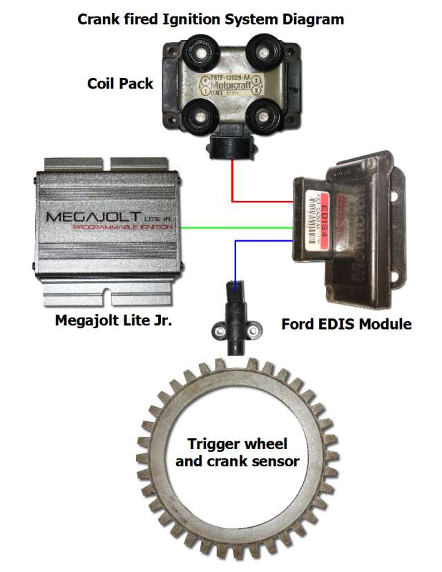


Mjlj V4 Vehicle Installation Guide Autosport Labs


Chevrolet Car Pdf Manual Wiring Diagram Fault Codes Dtc
Jan 11, 19 · The most common type PT100 has a resistance of 100Ω at 0°C and 1384 ohms at 100°C RTDs come in 2wire, 3wire or 4wire versions The 2wire RTD signal is affected by the distance to the controller, but 3wire or 4wire RTDs can compensate for line losses Unlike thermocouples, special connection cables are not very necessary for PT100Aug 29, 18 · Tp100 Module Wiring Diagram 97 nissan sentra scannerdanner forum evinox modusat xr eco twin plate heat interface unit modules sel electric bmw e30 diagrams bimmertips com tp 100 datasheet mean well enterprises co ltd 4xrtd 4 hf 6es7134 6jd00 0ca1 general new also gets very hot fiat commscope yamaha dtxpress iv user abf gti pt100 in orJan 24, 19 · 1 Common Throttle Position Sensor (TPS) wiring diagram (wire color, terminalToyota T / I need a wiring diagram for I need a wiring diagram for a Toyota t pickup Help please ( Toyota T) Micah Keener in Edgefield, SC on August 11, Sign in to Answer Throttle Position Sensor Apr 05, · I need a full wiring diagram from a T 4x4 A/T


Kteb 2c72 1 Tp Keystone Electronic Fluorescent Ballast


1998 Ford Expedition Engine Diagram More Diagrams Stage
Sep 01, 16 · The two computers have nothing in common Even if you had the wiring diagram, you would not be able to get the harness spliced because they are not hitting the ECU pins in the same location Example the 34 has individual wires form the ECU to each injector The 30 has all of the injectors on a common 2wire system (power and ground)16 The measurement between wire A and wire B will be over 100 ohms 17 The measurement between wire A and wire C will be the same 18 The measurement between wire B and wire C will be low, just the resistance of the wire itself 19 You will now have identified which wire is which Now connect them to the appropriatePage 10 LOCATING & MAKING CONNECTIONS ACCESSORY WIRE(S) THAT POWER THE HEATER/BLOWER MOTOR (12V in run or on positions) This wire is also in the main ignition switch harness usually located in the steering column Make all connections as close to the ignition switch harness as possible Use the diagram below to create a circuit that will


Tp100 Module Wiring Diagram Dicktator Connection Diagrams September 09


Dicktator Connection Diagrams September 09 Ignition System Fuel Injection
Fuel pumps & accessories;Apr 26, 18 · rtd pt100 3 wire wiring diagram – What is a Wiring Diagram?
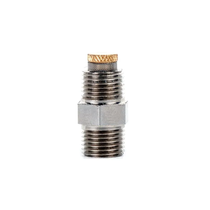


Dicktator Single Coil Ignition Module Incl Plug Pins


Ezk Ipdown Net


Ignition Modules Diesel Electric


Modusat Tp 15 Installation Guide Manualzz


I O Types


How To Wire Water Heater Thermostats


I Believe The Thing I Need Is A Wiring Diagram For A 1998 Olds 3800 Series It Has A No Spark Condition It Does Have


1993 Buick Lesabre Engine Diagram Home Wiring Diagrams Action


Dictator 60 2 Install Bmwfanatics


Electrical Wiring Diagram Of Motorcycle Http Bookingritzcarlton Info Electrical Wiring Diagra Electrical Wiring Diagram Motorcycle Wiring Electrical Diagram


Zing Ear Tp 01 Zh Touch Lamp Light Dimmer Switch Control Sensor Amazon Com


Part 1 How To Test The 1 8l Vw Ignition Control Module And Ignition Coils


Gotech Mfi Manual Manualzz
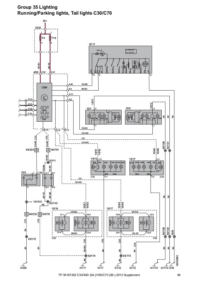


Tp 10 C30 S40 V50 C70 Supplement Wiring Diagram


What 4 Pin Hei Module You You All Use Team Chevelle


Ecu Grounding The Dos And Donts Haltech


1999 Pontiac Bonneville Engine Diagram Wiring Diagram Post Speed
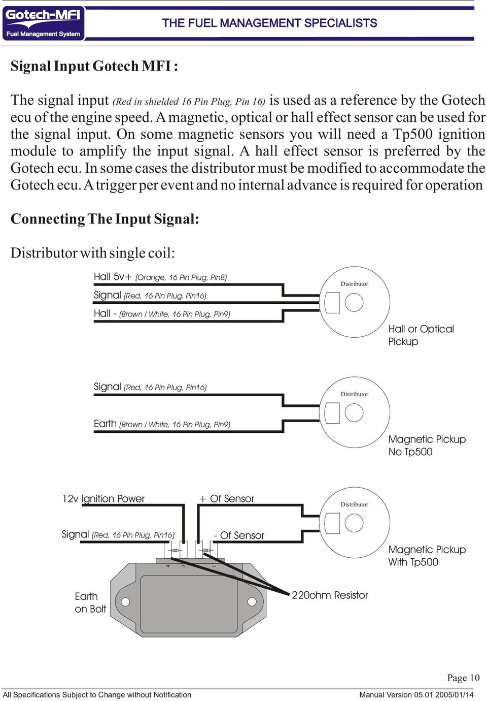


Mfi Instructional Manual Version Pdf Free Download
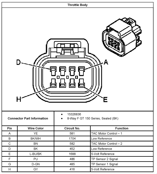


5 3 Wiring Harness Wiring Diagrams Here Page 2 Ls1tech Camaro And Firebird Forum Discussion


Schematic Wiring Diagram Apps On Google Play
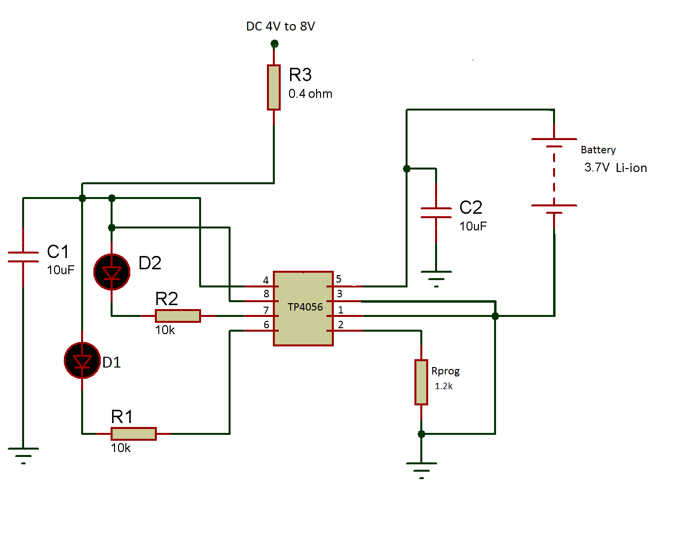


Make A 3 7 V Li Ion Battery Charger Using Tp 4056 Part 9 9


Amazon Com Durablow Fireplace Electronic Ipi Pilot Ignition Control Module Replaces Dexen 593 592 Gm 6ka Hearth Home Technologies Hht 350 M Home Kitchen


I O Types
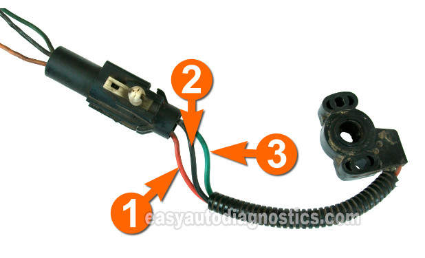


Part 3 Throttle Position Sensor Tps Test Ford 5 0l 5 8l


Tp100 Vw Conversion Wiring Len Gerber Len Gerber Flickr


Tac Module C2 Part 2 Gif 11 6 98 Chevy Silverado Chevy Silverado Garage Equipment


Ignition Module Tp100 Opel Kadett Monza Rekord Speedquip


Ignition Coil Distributor Wiring Diagram Wiring Forums Automotive Mechanic Automotive Electrical Auto Repair


Dictator 60 2 Install Bmwfanatics


Tp 100b Datasheet Pdf Mean Well Enterprises Co Ltd


July Timer Instructions


Tp100 Wiring Diagram Wiring Diagram For A Usb Cable M Au Delice Limousin Fr


Tp100 Wiring Diagram 01 Chevy Cavalier Coil Wire Diagram Rccar Wiring Nescafe Jeanjaures37 Fr


Power Esp32 Esp66 With Solar Panels And Battery Random Nerd Tutorials


Kteb 2 1 Tp Emi Keystone Ballast


Tp 0625 001c 816 Audio System Installation Guide
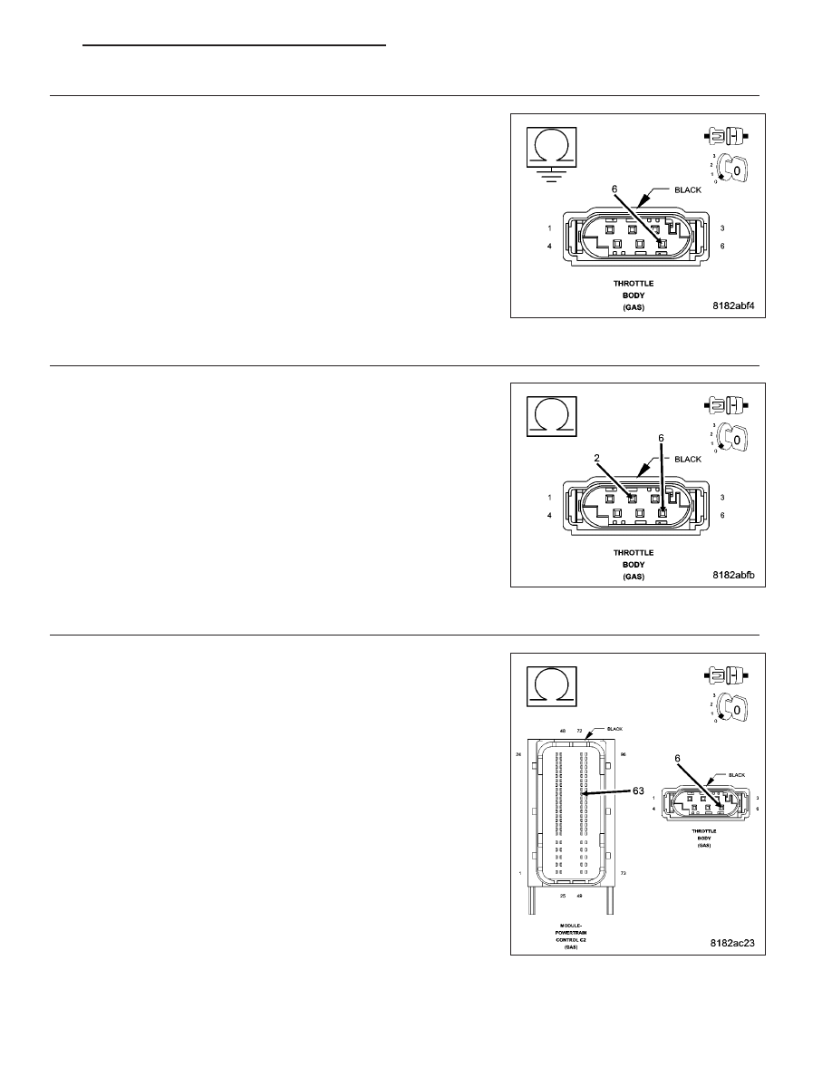


Dodge Caliber Manual Part 730
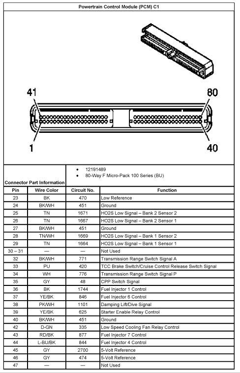


5 3 Wiring Harness Wiring Diagrams Here Ls1tech Camaro And Firebird Forum Discussion
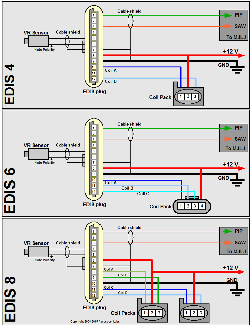


Mjlj V4 Vehicle Installation Guide Autosport Labs
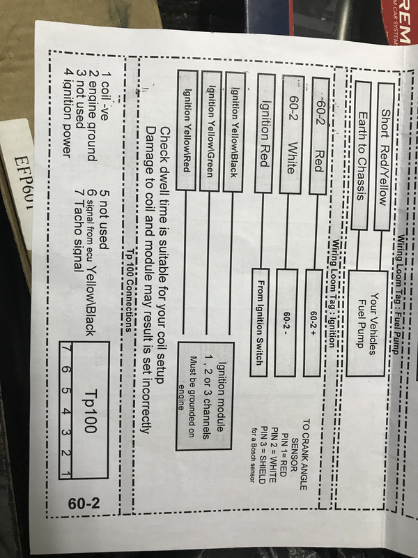


Dicktator Issues Help Please The Volkswagen Club Of South Africa


Car Remote Starter Installation 11 Steps Instructables
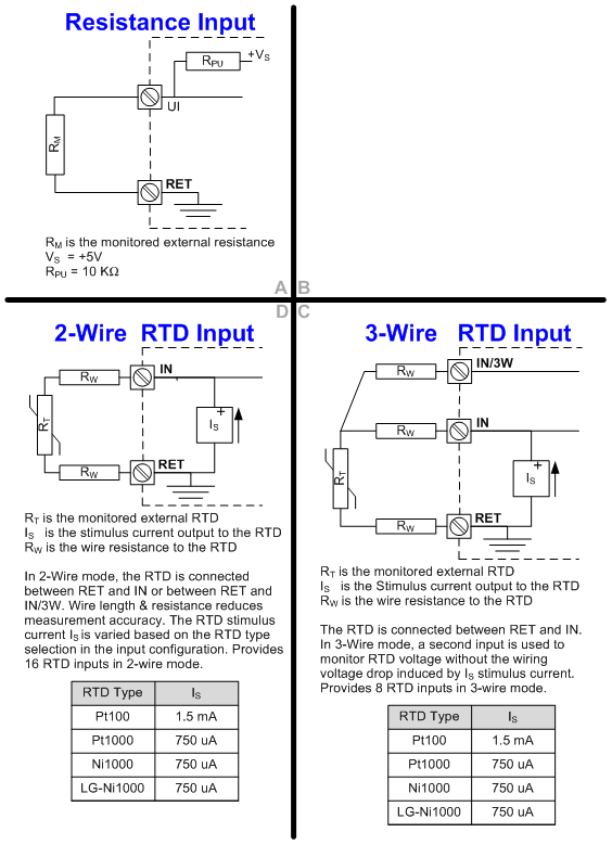


I O Types


Ignition System With Hall Effect Sender


Coil Induction Wiring Diagrams Youtube


Ignition System With Hall Effect Sender


Module Circuits Wiring Diagram Youtube


Wouter S Page The Retro Society Of Reverse Engineering And Taking Things Apart
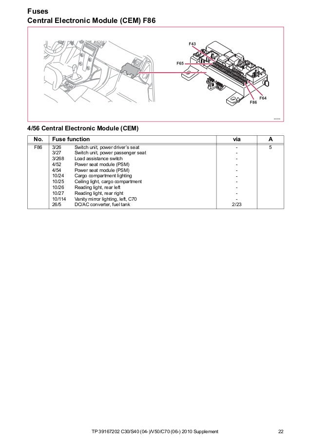


Tp 10 C30 S40 V50 C70 Supplement Wiring Diagram


Dicktator Std Assist Needed The Volkswagen Club Of South Africa


I O Types


Tp100 Wiring Diagram Chevrolet Wiring Harness Diagram Tekonshaii Corolla Waystar Fr


0 件のコメント:
コメントを投稿